📅 January 06, 2020
•⏱️5 min read
Repairing a Nextbase 412GW Dashcam
I've had my dashcam for around 2 years and it's been fantastically reliable right up until the last month or so where it hasn't been very happy at all. Losing settings, not recording when it should and general other strange gremlins. Formatting the SD card on a desktop machine would be the first port of call for any recording issues but this was slightly different. I did the format anyway, it didn't help. It was the inability to save settings that rung a bell, I have had similar experiences with old PCs and other equipment whose motherboard battery had failed. I also noticed that once the car was switched off, the dashcam might last just a few seconds under its own steam before powering off again. Unlike the usual 10 mins or so. Having decided the battery was at fault, it was time to pull it apart. This is on my 412GW, but it'll probably translates well to other models too.
What you'll need
- Patience and a steady hand.
- Precision screwdriver set or very small Phillips and flathead screwdrivers.
- Plastic case opening tools, these can be bought but small tough non-metallic household items can be used. Guitar picks are great for this.
- Needle nose tweezers, ideally with non-metallic tips.
- Soldering iron.
- Replacement Battery. A bit more on that...
About the battery
I found it impossible to find an identical battery. It's either an old format or was especially made for Nextbase. So I took a punt on one as close as I could get in the hope that it would fit, it did. The LiPo battery that I took out was a 462530 3.7v 280 mAh battery. Whilst googling I learnt that the numbers refer to the physical size of the battery, so this one was 47mm x 25mm x 3mm. Couldn't find it anywhere. So, I went with a 303030 battery, this was only available as a 210mAh capacity, but that was fine, we don't need long life off car battery power. It fits just fine. Specifically, I used this one https://www.aliexpress.com/item/33019213260.html
Disassembly
Be aware that this is a battery-operated thing so it should be considered as switched on all the time, don't go poking around the board with metal screwdrivers.
- Switch off the camera and remove the SD Card.
- Remove the four Phillips screws in the casing, two on the top near the docking port and two on the bottom. Put them to one side.
- Carefully prise apart the casing along the seam: I found it easiest to start at the top near the docking port. The case is held together with snap together tabs that are quite robust and open with a pop. I found them quite sturdy but don't panic if one or two of these tabs break, it will go back together just fine.
- Stand the camera on the lens housing. The outer screen casing can now come away towards you and can be safely folded down below the unit, being careful not to touch the inside surface of the screen (fingerprints). Take a look inside the screen cover and take note of the ridges that hold the LCD in position, this will be important later.
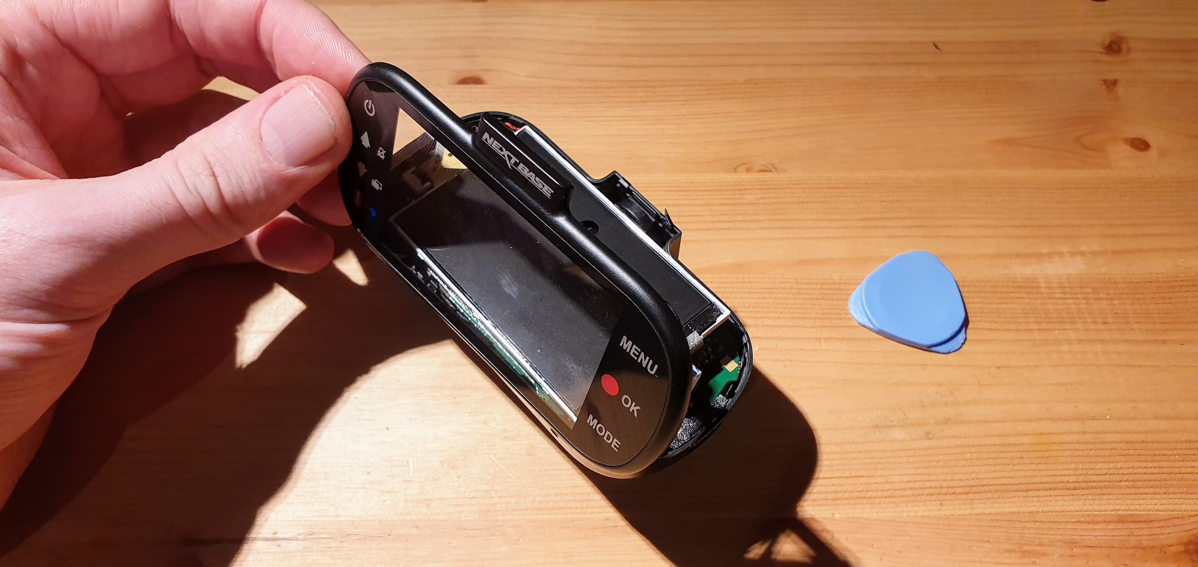
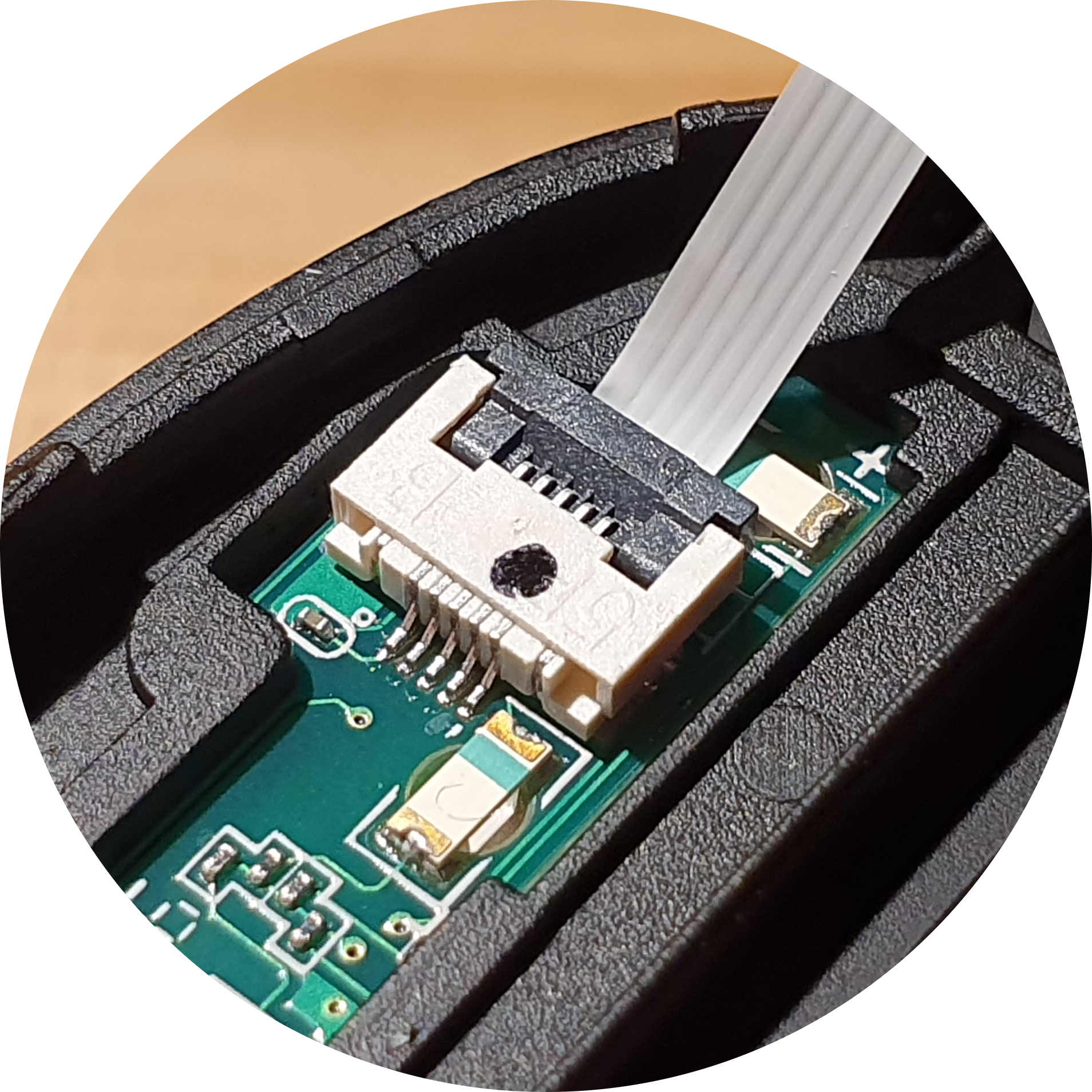
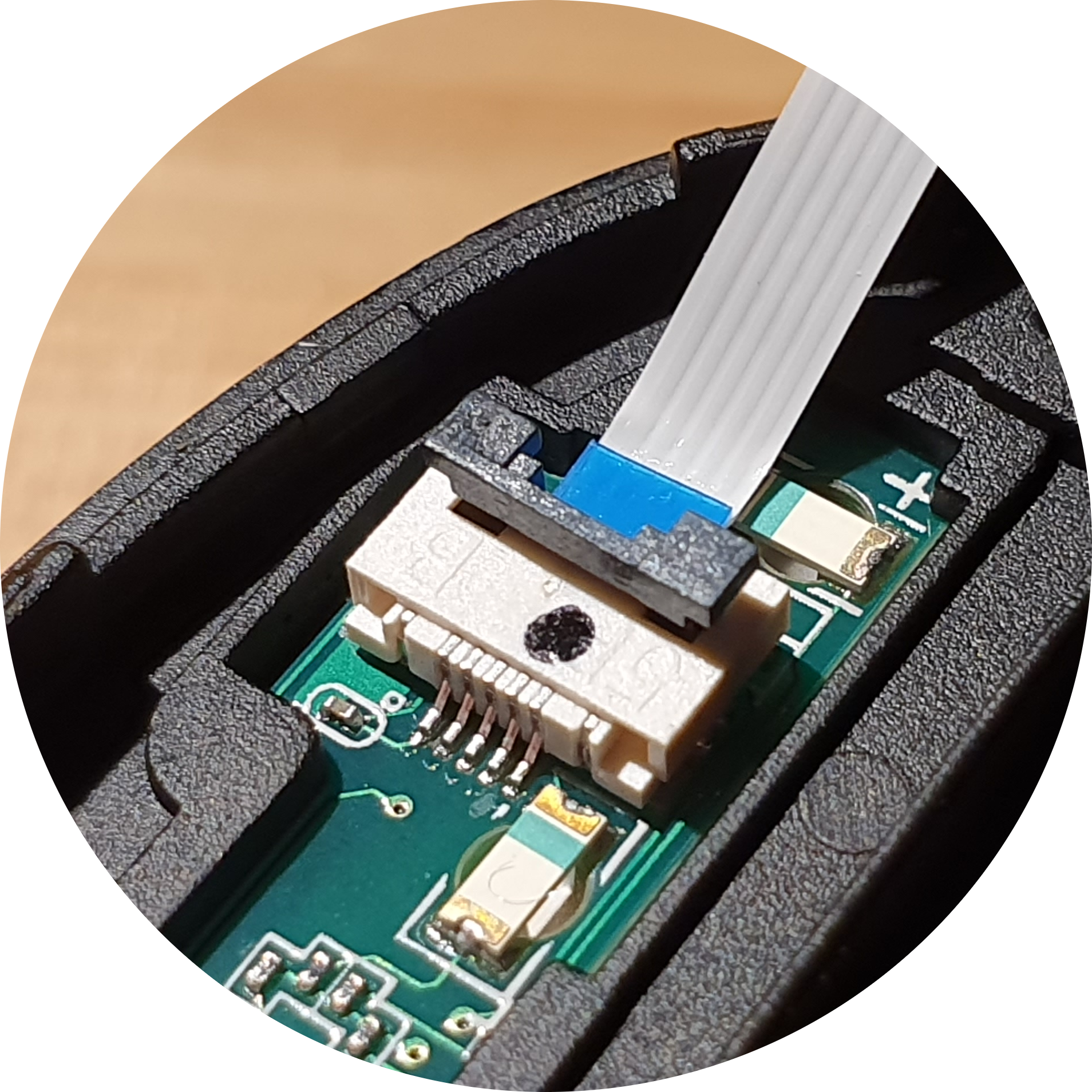
- Remove the two ribbon cables from the front screen casing and put it to one side. The ribbon cable connectors can be released by lifting the black locking tab.
Locked position:
 Open position:
- The LCD screen is attached to the board below with a ribbon cable, with the cable staying connected, the screen can be safely opened like the back cover of a book from left to right to show the board underneath.
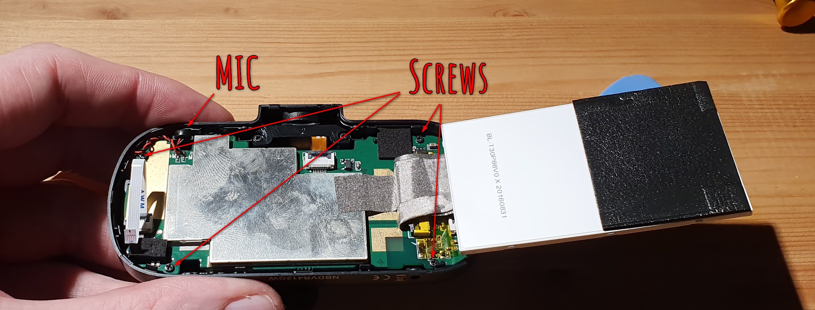
- Lift the microphone out of its housing slot gently pulling on the cables towards you, it should slide out.
- Remove 4 screws from 4 corners of the circuit board. These are very slightly different to the 4 from the outer case so keep them separate.
- Disconnect the ribbon cable at the top.
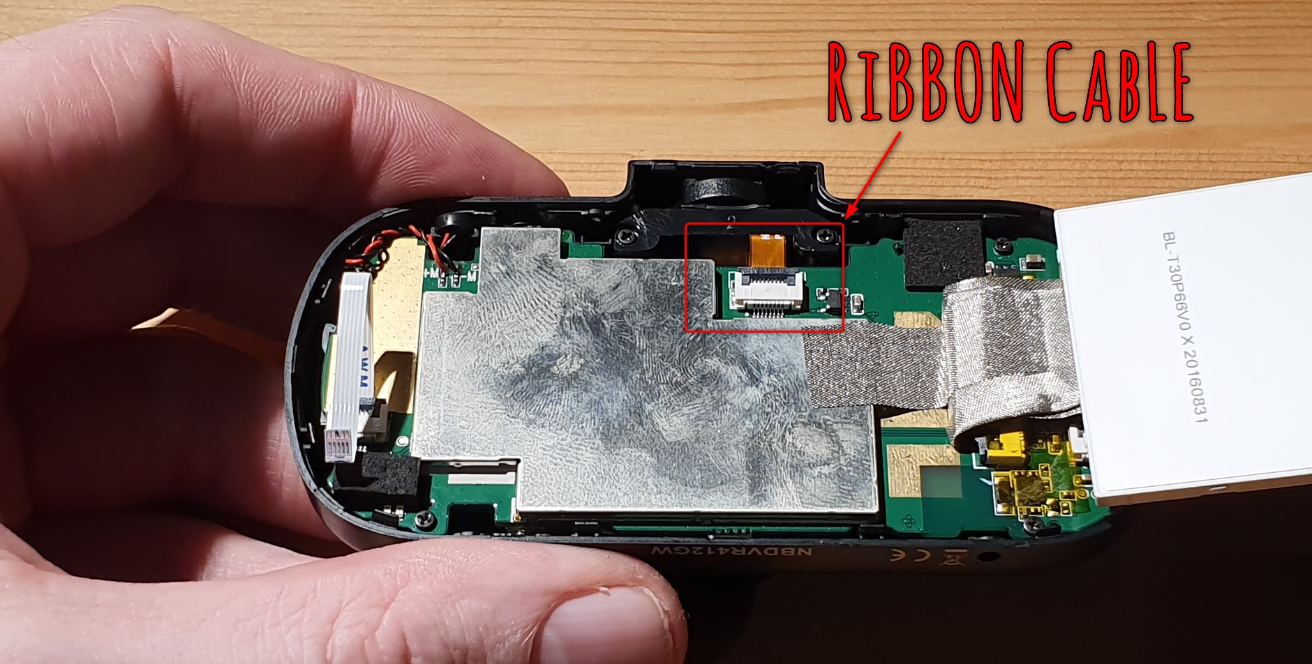
- There are connections on the back of the circuit board so it can't be completely removed. Keeping an eye on the USB and AV out ports, lift the board from the bottom, lifting towards you and with a downward motion until the ports clear the housing, the board can be lifted a little. It's now a good idea to carefully roll the camera towards you so it is sitting upright.
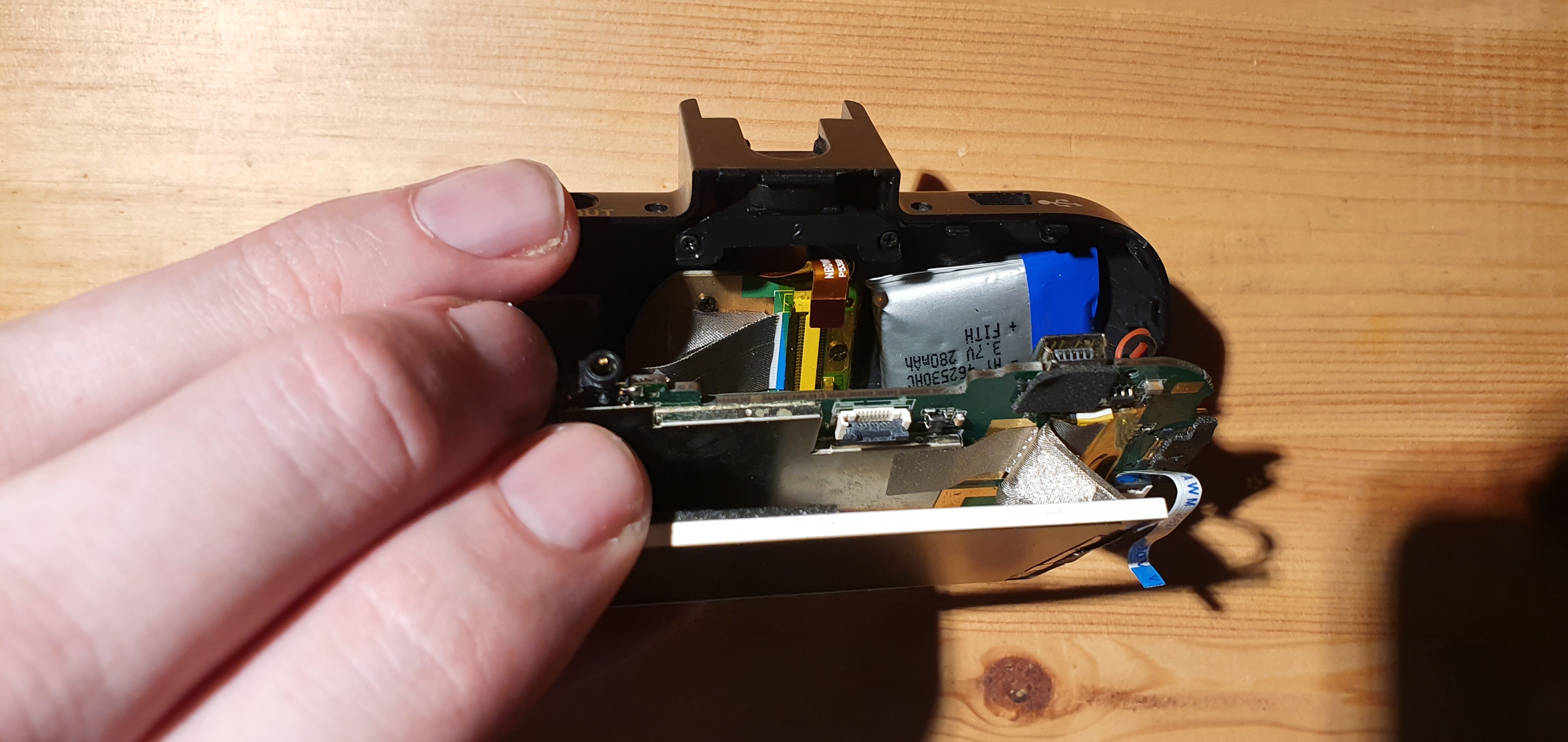
- There is a wide ribbon cable connecting the board and camera module. This can be disconnected at either the board or the module. Using the tweezers peel back a cm or two of the silver tape, lift and disconnect the cable from the connector. The board can now be safely folded down.
Replacing the Battery
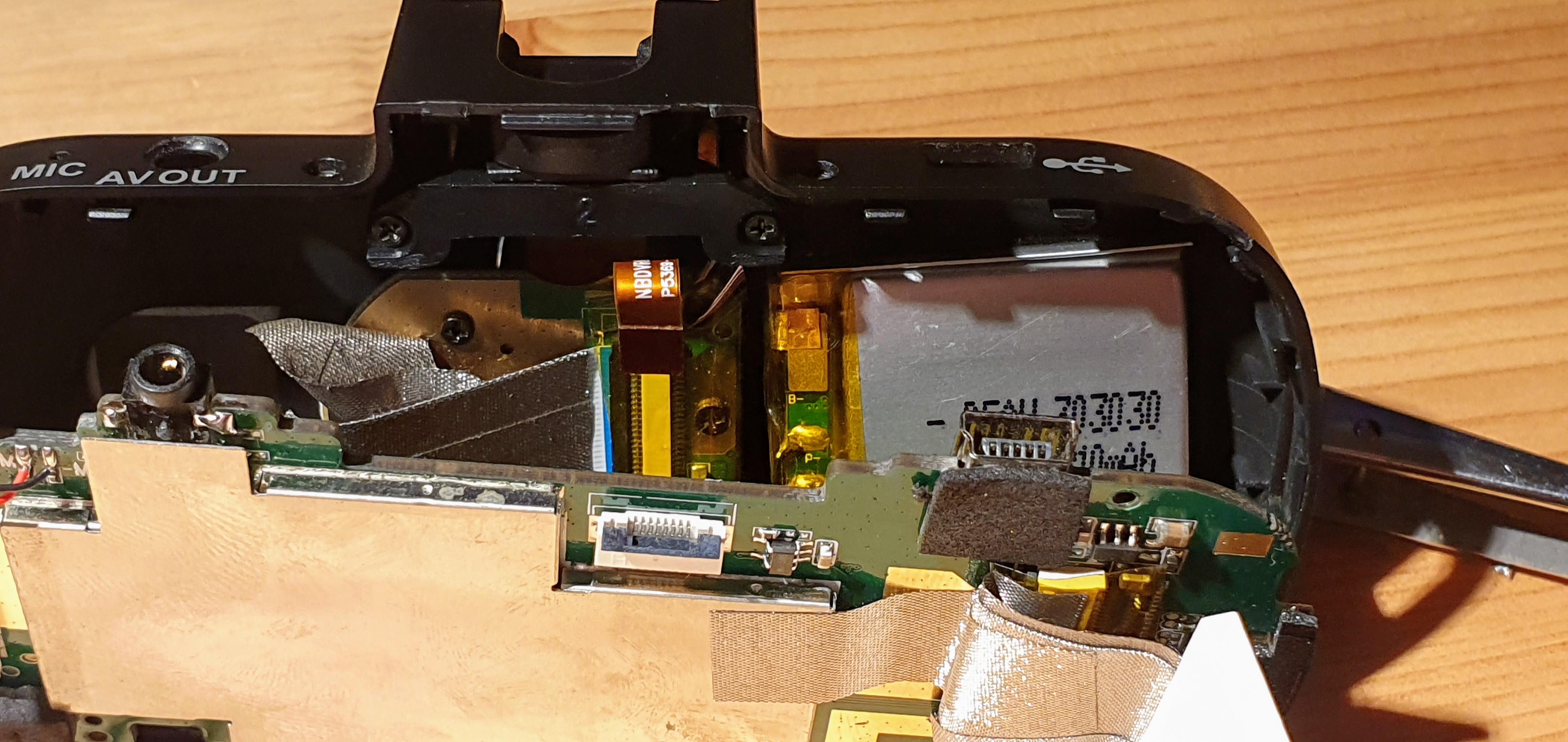
Now we can access the battery. It is secured with some very strong double-sided adhesive foam. Gently prise the battery free with a blunt, non-metallic object. DO NOT PIERCE THE SILVER BATTERY WRAPPING. It takes some time but better to be cautious.
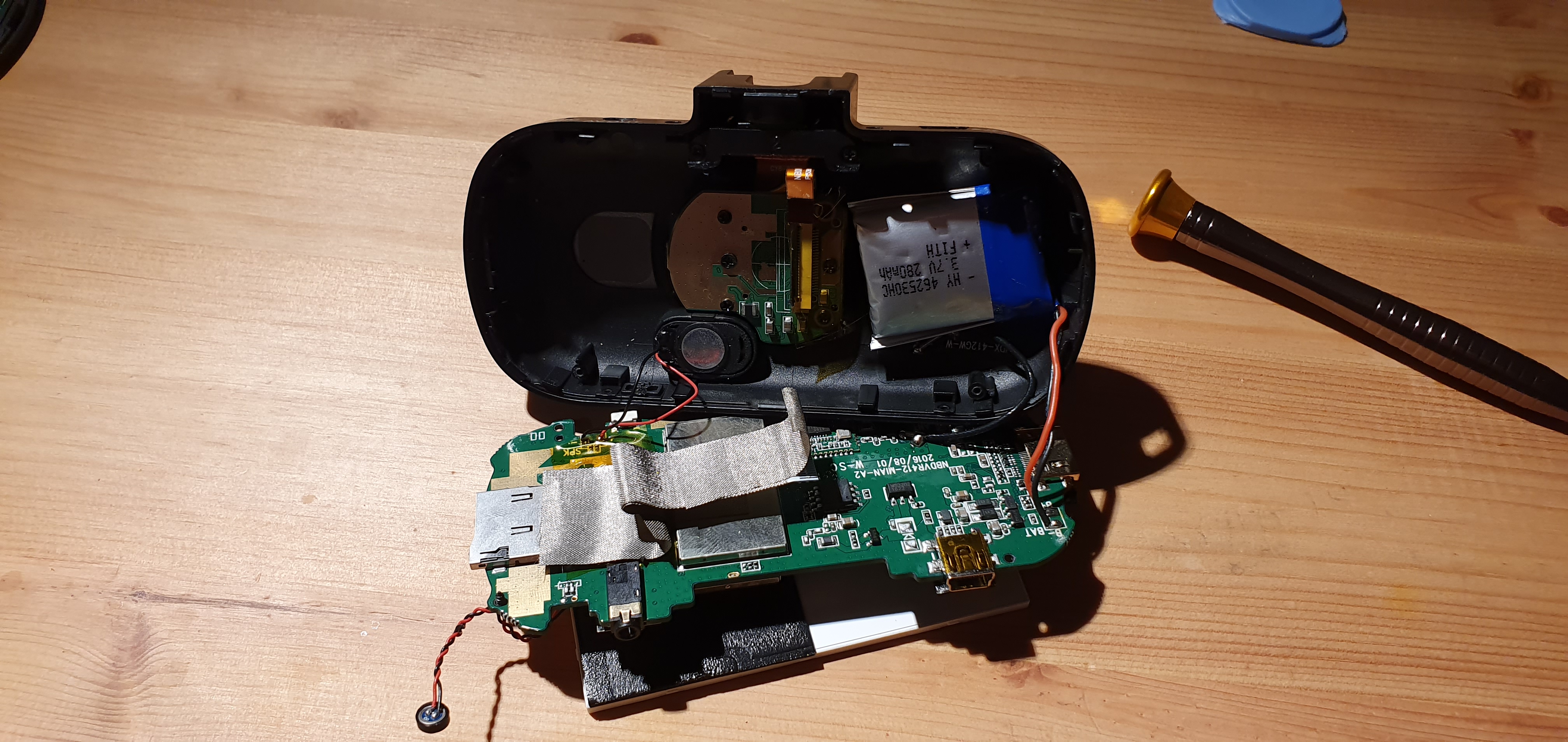 My battery was really bloated. I'm not particularly experienced with LiPo batteries but apparently this isn't unusual for an old battery and isn't likely to explode unless I help it along.
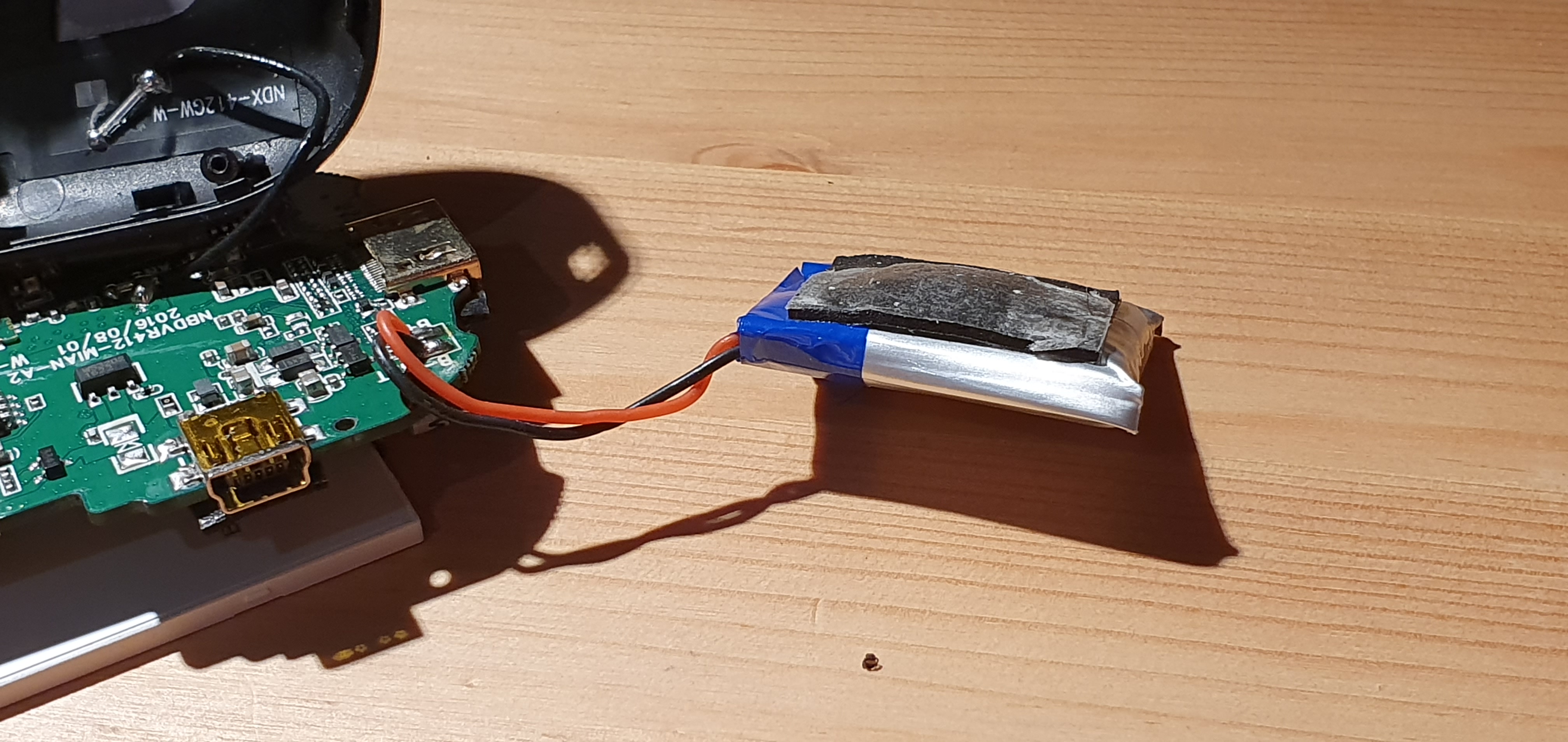 De-solder the battery and solder on the new one taking care not to touch the wires together on either. Positive (red) nearest the USB port.
The battery will sit in the casing in the originals place without too much trouble I did not replace the sticky foam as the wider replacement feels quite secure and it couldn't move once I'd put the circuit board back in.
Re-assembly
- The exact reverse of above.
- Re-connecting the ribbon cables can be tricky, use the tweezers being careful not to touch the cable contacts (if they're metallic) and make sure the cables are all the way home in the connectors before locking them down again.
- Be careful not to pinch the new battery cables when replacing the board and don't forget the small central ribbon cable.
- Once the board is back in place make sure the external ports are aligned before screwing it back in and test the reset button at the bottom to make sure you get a positive click.
- Push the microphone back in place.
- When it comes to replacing the front panel, you may find it easier to stand the panel behind the camera body for the right angle to get the ribbon cables back in.
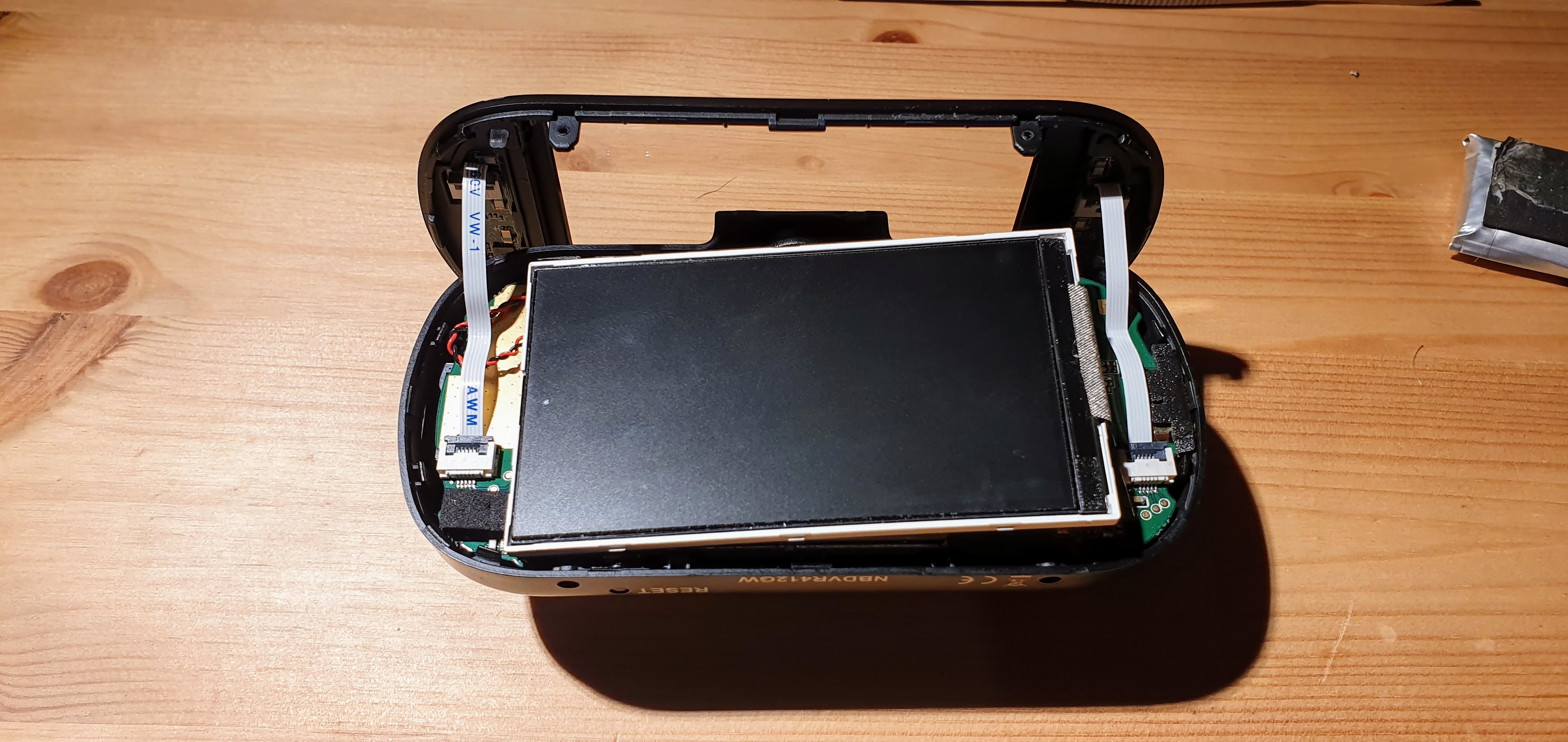
- Once the two ribbon cables are in it's now possible to turn the camera back on by accident by touching the buttons. I did, and it made be jump a little.
- Check that the LCD is within those ridges before pressing home the front cover going round and clicking the tabs back into place and replacing the screws.
Done
Hopefully you now have a working dashcam that will serve another couple of years until the battery needs replacing again.
